
Why wrinkles matter
Wrinkles in blown film are more than a cosmetic problem. They can make winding unstable, reduce usable width, create converting problems and lead to customer complaints. In many cases, a wrinkle is a symptom of uneven tension across the web. The imbalance is created somewhere between the die exit and the nip rolls, and it may become visible only when the bubble is collapsed.
The important point is not only to remove the visible wrinkle. The real task is to find where the tension difference begins. A wrinkle seen at the collapsing frame can start much earlier in the process, for example at the die, the air ring, the frost line, the bubble cage or in the downstream web handling system.
Most wrinkles are created by a difference in path length, cooling, friction or web tension. If one lane becomes loose while another lane is tight, the loose lane has excess film length and starts to fold.
How wrinkles form during collapsing
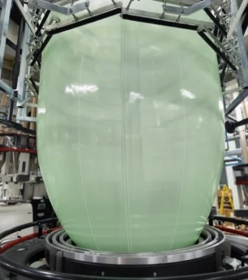
When the bubble is stable, centred and cooled evenly, the film travels from the die to the nip in a controlled and symmetrical way. When the bubble is moving, eccentric, poorly supported or cooled unevenly, different points around the circumference travel different path lengths to the collapsing frame and then to the nip rolls.
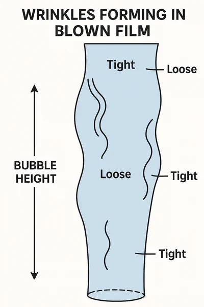
Short paths become tight. Long paths become loose. The loose lanes are the lanes that normally wrinkle during collapsing. This tight and loose banding is often the first clue that the root cause is bubble motion, uneven cooling, unstable output or machine alignment.
The collapsing frame may only be showing the problem. It is not always the source of the problem. Before adjusting the collapsing frame too much, check if the bubble, frost line, cooling and web path are stable.
What to look forTight and loose lanes are one of the most practical ways to understand wrinkles in blown film.
Where the wrinkle starts matters
The first visible wrinkle is not always the real cause. Wrinkles can start in the melt flow, the die, the air ring, the bubble, the collapsing frame, the nip rolls, the winder or the idler rollers after the nip.
A good diagnostic method is to divide the line into zones and work upstream step by step. First confirm where the wrinkle becomes visible. Then check the nearest upstream zone. If that zone is stable, continue upstream until the real source is found.
This approach avoids random adjustments. It also helps operators document what was checked, which setting was changed and whether the change improved or worsened the film.
Melt and die
Output, pressure, melt temperature, die centring, lip condition and gauge profile.
Cooling and bubble
Air ring, IBC if installed, frost line height, BUR, drafts and bubble support.
Collapsing and web handling
Collapsing frame, nip rolls, idlers, tension, friction, winding and roller condition.
Common wrinkle patterns
Wrinkles do not always look the same. Their pattern can help the operator understand where to start checking. The same visual defect can still have more than one cause, but the pattern gives a useful direction.
- Edge wrinkles: Often related to uneven tension at the edges, poor bubble centring, edge cooling differences or uneven collapsing.
- Crease lines: Sharper folds that can come from collapsing, nip pressure, winding or local web handling problems.
- Diagonal wrinkles: Often indicate twisting, shear, roller misalignment, bubble movement or uneven pull across the web.
- Repeating wrinkles: Often linked to a roller, bearing, damaged surface, winding issue or a repeated mechanical contact point.
- Random wrinkles: Often linked to bubble breathing, unstable output, air movement, IBC variation or inconsistent film temperature.
Material influence: stiff and ductile resins
Film extensibility and stiffness influence how strongly a tension difference becomes visible. Less extensible films, including many HDPE structures and some PP, PA and barrier films, can show wrinkles more clearly because they have less ability to redistribute local strain. The effect depends on the complete film structure, gauge, temperature and orientation, so crystallinity alone should not be treated as the cause.
Softer and more ductile materials, such as LDPE, LLDPE and EVA, tolerate small tension differences better. They can stretch slightly and may hide minor variations that would be visible in a stiffer film.
Wrinkle sensitivity also depends on film gauge, film temperature at collapsing, coefficient of friction, slip level, surface condition, line tension and the total time the film remains soft before it is fully supported.
If you run stiff resins, high clarity film, thin film or barrier structures, plan for tighter control of melt temperature, bubble stability, frost line height and collapsing conditions. Additional bubble support may also be needed.
Main root causes and practical fixes
Wrinkles usually come from a combination of process, material and mechanical conditions. The best result is normally achieved by stabilising the process first and then correcting the mechanical web path.
Melt temperature, pressure and output variation
A common driver of bubble movement is non-uniform melt temperature, unstable output, unstable pressure, die flow variation or gauge variation. Local hot or cold areas leaving the die react differently to air ring cooling. The bubble may then move or hunt, creating tight and loose lanes.
Air ring blowers and IBC controls should be checked, but the deeper fix is often to stabilise and homogenise the melt. This can involve reviewing the barrel temperature profile, screw condition, screen pack condition, die temperature control and the amount of shear heating in the process.
- Adjust the barrel profile in small controlled steps, based on the polymer, screw design, output rate and machine limits.
- Avoid sharp temperature differences unless there is a specific process reason.
- Confirm that motor amps, melt temperature and head pressure are stable.
- Check for dirty screens, flow restriction, die build-up, unstable dosing or worn screw flights.
- If temperature still varies, inspect the screw and die flow path.
BUR, frost line height and cooling geometry
Blow up ratio, or BUR, changes bubble diameter and molecular orientation, but it should not be used as a stand alone wrinkle diagnosis. Wrinkle sensitivity is better assessed together with drawdown ratio, die gap, frost line stability, cooling balance and the amount of unsupported soft film between the die and the first effective bubble support.
When layflat is fixed by the product, focus on stable and uniform cooling and on supporting the bubble without restricting it. The objective is a centred bubble with a stable frost line and a controlled path into the collapsing frame, not simply a larger bubble diameter at the air ring.
- Change BUR only when the product specification allows it, and evaluate the result together with drawdown, frost line and bubble stability.
- Stabilise frost line height before making large mechanical changes.
- Check air ring lip gap, blower output, filters and cooling air distribution.
- Consider a conical upper lip, longer intermediate cone, two closely stacked rings or an air ring better sized for the product.
- Remove external drafts from doors, fans and ventilation.
Insufficient bubble guiding or shielding
If the melt is stable but the bubble still moves, mechanical support may be needed. Roller-type bubble cages are widely used. For some softer films, low-friction slats can also help.
For less extensible or difficult films, adjust the bubble cage close enough to the stable region of the bubble to control lateral movement, but not so close or tight that it adds drag, marks the film or disturbs cooling. The best position depends on the material, frost line and cage design.
- Use the bubble cage to support, not squeeze, the bubble.
- Check that cage rollers rotate freely and are clean.
- Keep the tower area protected from drafts and air turbulence.
- Make sure the bubble is centred before correcting downstream tension.
Collapsing frame and nip rolls
The collapsing frame is where many wrinkles become visible, but it is not always the original cause. Closing the collapsing frame can reduce the path length difference between centre and edge, but it also increases contact area and drag.
Too much drag can create new wrinkles, especially with high-friction film, warm film or film with low slip level.
- Check collapsing frame angle and symmetry.
- Inspect frame surfaces for wear, contamination and friction differences.
- Check nip roll parallelism, pressure and surface condition.
- Avoid solving one wrinkle by creating another friction problem.
IBC and bubble control, if installed
If the line has internal bubble cooling, IBC variation can create bubble breathing and position changes. Sensor drift, leaks, condensation or valve instability can move the bubble and create uneven tension during collapsing.
Not all blown film lines have IBC. If IBC is not installed, focus on air ring balance, bubble cage position, tower drafts and normal bubble stability.
- Clean and recalibrate IBC sensors.
- Check valves, hoses, seals and leaks.
- Check for condensation or blocked air paths.
- Confirm that bubble diameter control is not hunting.
Moisture, contamination and material preparation
Moisture is especially relevant with hygroscopic materials, wet regrind, wet additives, PA, PET, EVOH and contaminated material streams. For standard PE film production, drying is usually not the first check, but wet regrind or wet additives can still create process instability.
Gels, contamination and unmelted material can also create local thickness variation and start a crease.
- Check material storage and moisture exposure.
- Check dosing of regrind, additives and masterbatch.
- Clean screens and inspect for gels or contamination.
- Use controlled material preparation when running sensitive polymers.
Downstream rollers and winding
Poor downstream web handling can re-introduce wrinkles even when the bubble is stable. Seized bearings, dirty rollers, wrong roller crown, uneven tension or poor winding geometry can all create local drag and folding.
If the wrinkle starts after the nip, the extrusion process may be stable and the problem may be in the web handling section.
- Inspect every roller in the path.
- Check bearings, roller surface, diameter and alignment.
- Check winding tension and taper tension settings.
- Make sure the web is not steering or rubbing on side guides.
Fast diagnostic pathway
Use a simple and repeatable check sequence. This helps operators avoid random adjustments and makes the process easier to document.
Mark the defect position relative to the tower and then use any available die, air ring or haul off rotation deliberately. A mark that remains fixed relative to a downstream roll or collapsing component usually points to that fixed hardware. A mark tied to a rotating die or air ring should move with that component relative to the tower. If the die and air ring rotate together, rotation does not by itself separate one from the other.
Quick troubleshooting table
The table below gives practical starting points. It does not replace proper line diagnosis, but it helps the operator decide where to look first.
| Symptom | Likely direction to check | Practical first action |
|---|---|---|
| Wrinkles start at collapsing frame | Bubble movement, uneven cooling, wrong frame angle, friction difference | Centre bubble, check air ring, reduce drafts, check frame symmetry and surface friction |
| Edge wrinkles | Poor edge tension, edge cooling, bubble not centred, collapsing geometry | Check bubble centre, air ring balance, edge temperature and nip pressure |
| Diagonal wrinkles | Twist, roller misalignment, uneven pull, tower alignment | Check tower alignment, nip parallelism, idlers and film path |
| Random wrinkles | Bubble breathing, IBC hunting, unstable output, drafts | Stabilise output, IBC and air ring; remove air turbulence |
| Wrinkles after nip | Downstream web handling or winding tension | Inspect idlers, bearings, web path and winding tension |
| Wrinkles with stiff materials | Low ability to stretch and equalise tension | Lower sensitivity by stabilising melt, reducing BUR if possible and improving bubble support |
| Wrinkles after material change | Different stiffness, COF, melt strength or temperature window | Recheck temperature profile, frost line, tension and collapsing setup |
Preventive practices
Wrinkle prevention is easier when the line has a stable reference setup for each product. A simple process record can save many hours during later troubleshooting.
- Keep process records: Record zone temperatures, melt temperature, motor amps, head pressure, BUR, frost line height, air ring settings and IBC settings for each job.
- Clean critical areas: Schedule regular cleaning of air ring lips, bubble cages, collapsing frames, nip rolls and downstream rollers.
- Maintain moving parts: Replace bearings before they seize and create local drag. Check roller surfaces and diameters.
- Prepare for difficult materials: For stiff resins, high clarity films or thin gauges, plan lower sensitivity settings before start-up.
- Train operators early: Teach operators to recognise tight and loose lanes before the wrinkle reaches the winder.
Testing film defects before full production
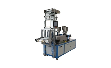
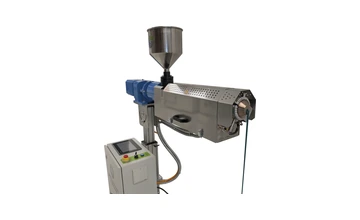
A laboratory blown film line can support operator training, material comparison and process development with lower material use than full production trials. It allows operators and technicians to understand how material stiffness, temperature profile, cooling, frost line height and collapsing behaviour affect the final film.
This is especially useful when testing recycled materials, new blends, bio based polymers, masterbatch changes or film structures that have a narrower processing window than standard production recipes.
Laboratory film testing can help operators understand film behaviour before full production.
Practical conclusion
Wrinkles are not random. They usually come from identifiable imbalances in path length, cooling, friction or tension. By stabilising melt temperature, reducing hot bubble exposure, supporting the bubble correctly and collapsing the film symmetrically, many wrinkle patterns can be reduced or removed.
The best troubleshooting approach is calm and systematic: locate where the wrinkle begins, divide the line into zones, check process stability first and then check the mechanical path. Change one thing at a time and document the result.
The information in this article is general guidance. The correct settings depend on polymer type, film structure, screw design, die head, air ring, cooling system and line layout. Always follow the documentation and safety instructions for the specific machine and material.
Need to test film behaviour before full production?
Green Extrusion Technology builds laboratory extruders and blown film test lines for material testing, teaching, R&D and small scale process development.
FAQ: wrinkles in blown film
What is the most common cause of wrinkles in blown film?
The most common cause is uneven tension across the web. The tension difference can come from bubble movement, uneven cooling, unstable output, collapsing frame friction, nip roll issues or downstream web handling.
Can the collapsing frame be the cause of wrinkles?
Yes, but it can also only make an upstream problem visible. Check bubble stability, cooling, frost line height and melt stability before making large collapsing frame changes.
Does high BUR create wrinkles?
BUR can influence bubble geometry and orientation, but it is rarely useful as a single explanation. Check BUR together with drawdown, die gap, cooling balance, frost line stability and bubble support, and change it only when the product specification allows.
Are stiff films more sensitive to wrinkles?
Yes. Stiffer films such as HDPE, PP, PA and some barrier structures have less ability to stretch and equalise tension, so small process differences become more visible.
Should operators change many settings at the same time?
No. The safest method is to change one variable at a time, record the result and then continue with the next check.